Hardware

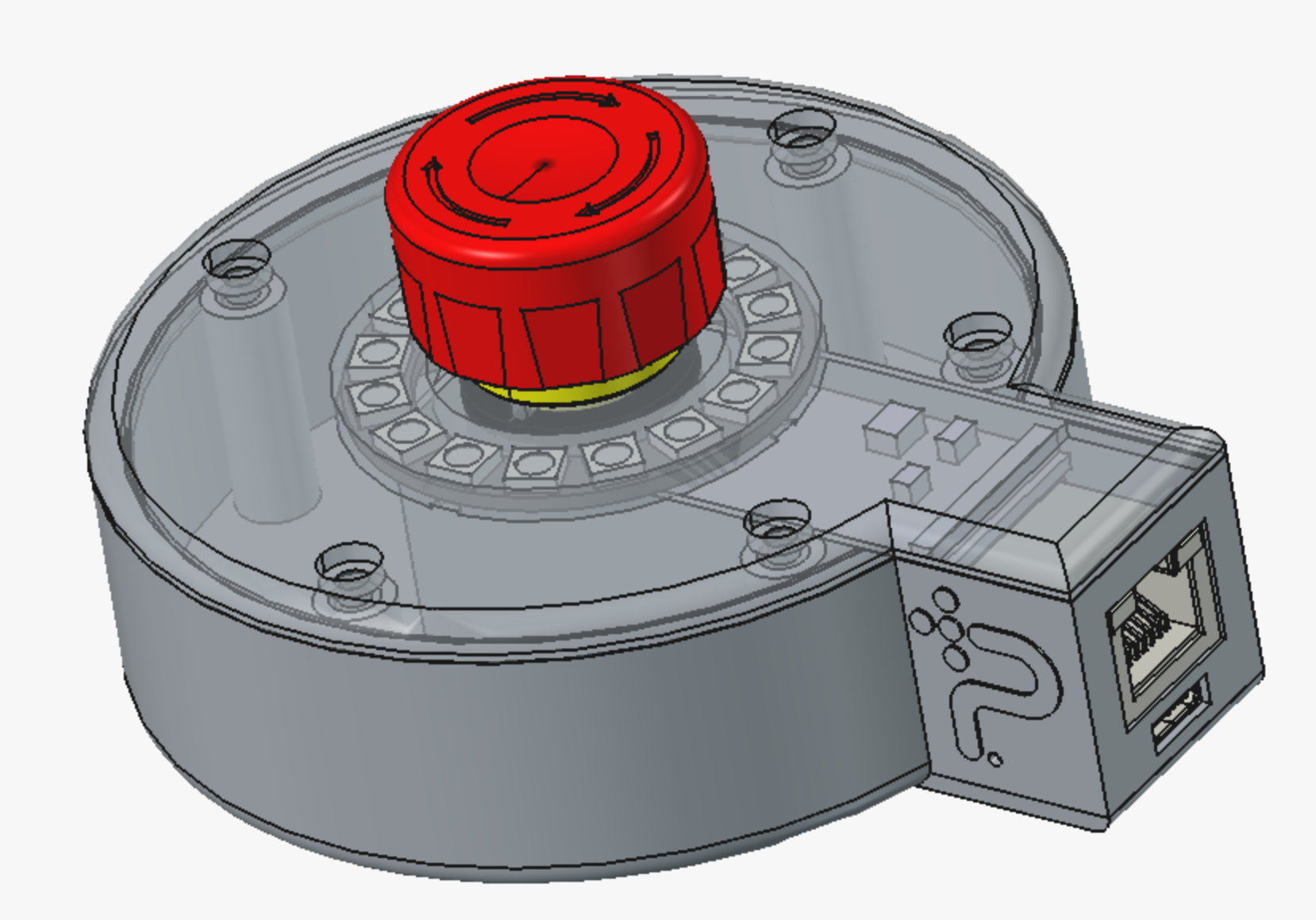
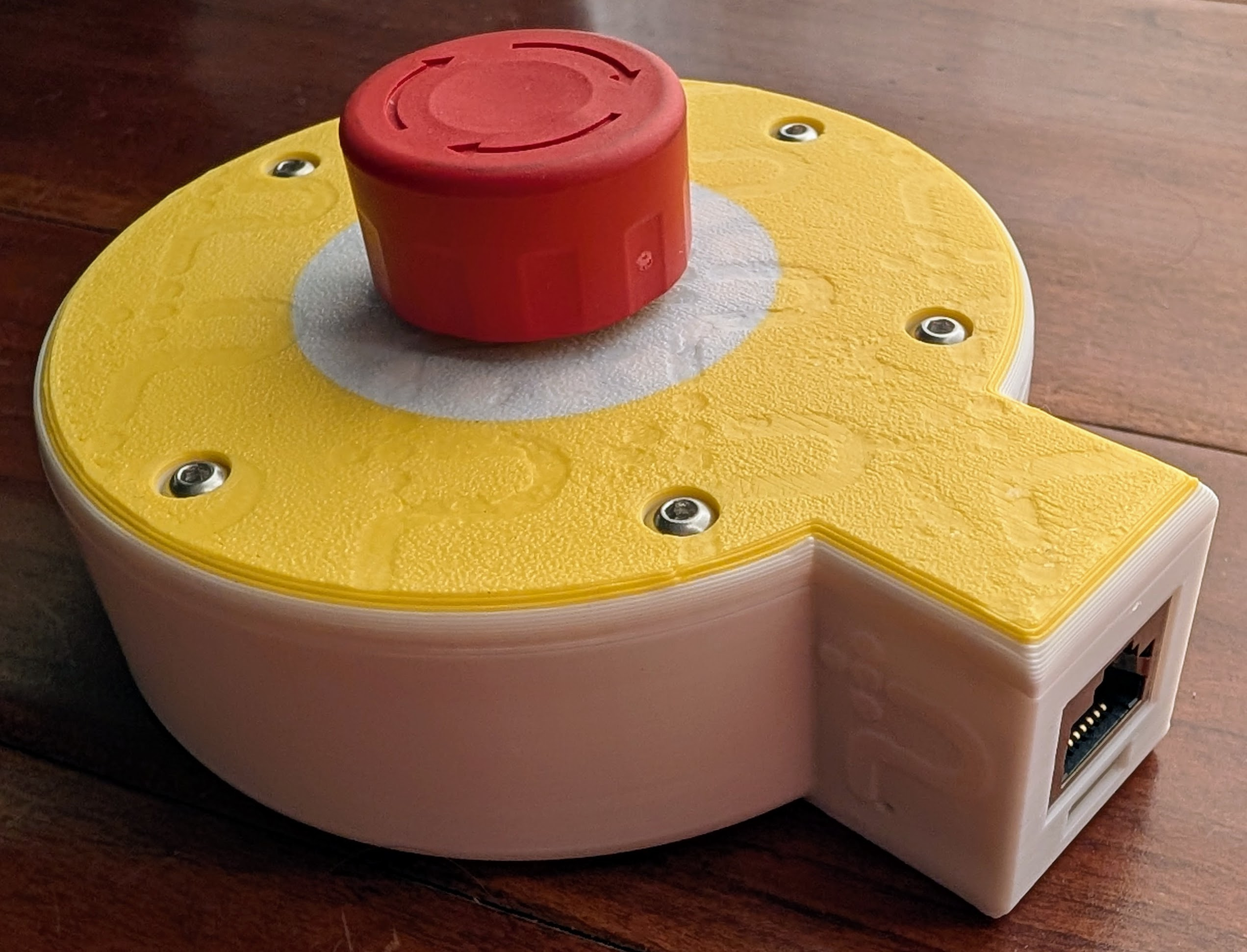
The physical design of the Protective Stop remote lives in hardware/ in the repository: enclosure CAD
(FreeCAD source casing.FCStd plus printable exports), the Waveshare
ESP32-S3-ETH carrier board (ESP32-S3-ETH-Schematic.pdf, photos, STEP), and
the LED and connector models. CAD render on the left, a printed unit on the
right: the E-stop button sits in the center, the LED ring lights the
diffuser around its base, and the Ethernet and USB-C ports live in the
side pod.
Build steps with photos: assembly guide.
Pinout and wiring
Two external parts connect to the board: the 16-LED WS2812 ring and a DPST normally-closed E-stop button. Each pole of the button sits in its own loopback: the firmware drives one GPIO and reads the echo on another, once per pole, so a broken wire reads the same as a pressed button (STOP). The pin assignments are fixed in the firmware; the wire colors are only an assembly convention to keep units consistent and easy to check. Pin names match the board silkscreen (IO17, IO39, and so on).
| Board pin | Goes to | Wire color |
|---|---|---|
| VBUS | Ring 5V | red |
| GND | Ring GND | black |
| IO17 | Ring DIN (data) | green |
| IO39 | Button terminal 11 (pole A) | white |
| IO40 | Button terminal 12 (pole A) | white |
| IO41 | Button terminal 21 (pole B) | yellow |
| IO42 | Button terminal 22 (pole B) | yellow |
Notes:
- The button contacts have no polarity; within a pole, either terminal can go to the drive pin. Keep each color pair on one pole: 11/12 together (white), 21/22 together (yellow).
- The sense pins are pulled down internally, so an open loop reads 0 and the firmware treats it as STOP. Pressing the button opens both poles at once; a single open loop (one broken wire) makes the two cores disagree, which also stops the machine.
- The ring can be installed in any of its 16 rotations. Which pixel counts
as LED 1 is a per-device setting, calibrated over the network after
assembly (
POST /api/ring_offset, seehttp_api.md). - The board's onboard status LED (IO21) needs no wiring.
Bill of materials
Everything except the printed parts is ordered online. Listings are pinned where the exact part matters; the wire and lid hardware are generic, so those stay as search links. All links open in a new window.
| Qty | Part | Notes | Order |
|---|---|---|---|
| 1 | Waveshare ESP32-S3-ETH | The W5500 Ethernet carrier board this design is built around. For PoE-powered units order the ESP32-S3-POE-ETH variant on the same page; it includes the PoE Module (B) that mounts on the board. | Waveshare |
| 1 | DIYmall WS2812B ring, 16 pixels | 5V addressable ring. | Amazon |
| 1 | NKK Switches FF0126BBCAEA01 E-stop button | Twist-release mushroom, two normally-closed contacts (DPST NC). Rated 100,000 operations (mechanical and electrical life, FF01 datasheet); the firmware counts presses against this in GET /api/health (CONFIG_DCS_BUTTON_RATED_OPS). The STEP model in this folder is this exact part. Substitutes must have 2NC: both loops need an NC pole, so a 1NO+1NC unit will not work; set the Kconfig rating to the substitute's datasheet value. | Octopart |
| 1 set | Silicone hookup wire | Red, black, green, white, yellow, 24 to 26 AWG, per the wiring table above. | search |
| ~6 | M3 socket-head screws + brass heat-set inserts | Lid fasteners. Confirm length and count against the current print before buying in bulk. | search |
| 4 | M1.6 heat-set threaded inserts, M1.6 x 5 x 2.5 mm | Anchor the ESP32-S3-ETH board to the base; 2.5 mm is the insert height/depth. | search |
| 3 | 1 oz (28 g) adhesive steel weights | Optional. Ballast in the base floor pockets so the unit stays put on a table. Wheel-weight style, adhesive backed. | search |
| 1 | Printed enclosure | print.3mf in this folder (base and lid; the diffuser is a white section of the lid print), or the pre-sliced print.gcode.3mf for an X1C. Not purchased; any common PLA/PETG works. | n/a |
Component datasheets
The design contains no custom electronics; the active components are all off the shelf, with freely accessible datasheets:
- ESP32-S3 datasheet (Espressif, via the Waveshare wiki)
- W5500 Ethernet controller datasheet (WIZnet, via the Waveshare wiki)
- ESP32-S3-ETH carrier board schematic (Waveshare)
- WS2812B datasheet (WorldSemi, the ring's LEDs)
- FF01 series E-stop datasheet (NKK Switches)
Licensing
The design is CERN-OHL-P-2.0 and the documentation is CC-BY-4.0; the full
texts live in LICENSES/. The vendor reference files
stay the property of their manufacturers and are included only as
fit-check references, with their origins listed below.
| File(s) | License / origin |
|---|---|
casing.FCStd, base*.stl, lid*.stl, led.stl, print.3mf, print.gcode.3mf | CERN-OHL-P-2.0 (original design) |
esp32-S3.step | CERN-OHL-P-2.0 (original board fit model) |
LED.step | CERN-OHL-P-2.0 (ring model commissioned by Polymath Robotics) |
enclosure-render.png, real.jpg, assembly/*.jpg | CC-BY-4.0 (original documentation) |
oshwa-certification-mark.svg | Official OSHWA wide certification mark generated for UID US002846; use is governed by the OSHWA certification agreement |
oshw-license-facts.svg | Generated with the Open Source Licenses Facts generator for this project's certified license combination |
ESP32-S3-ETH-Schematic.pdf | Waveshare, from the product wiki (direct PDF) |
ESP32-S3-ETH-details-15.jpg | Waveshare product photo, from the product page |
FF0126BBCAEA01.stp | NKK Switches E-stop model, from the NKK part page; series datasheet: FF01 (NKK) |
Design files
The editable source for the custom parts is casing.FCStd; the STL/3MF files
are its printable exports, and the STEP models are references used for fit.
Build steps live in the assembly guide.
OSHWA certification details and maintenance notes are in
oshwa_certification.md.