Assembly Guide
Building one Protective Stop remote takes about 15 minutes. Order the
parts from the BOM and print the enclosure
(print.3mf) first; the white diffuser is part of the lid print, not a
separate piece. Wire colors and pin names follow the
wiring table.
Tools: soldering iron (wiring and heat-set inserts), solder, flush cutters, wire stripper, Phillips screwdriver, 2.5 mm hex driver.
Printing the enclosure
print.3mf is a Bambu Studio project with everything preconfigured; the
plate holds two units (two bases, two lids). The reference setup, straight
from the project file:
- Printer: Bambu Lab X1 Carbon, 0.4 mm nozzle, textured PEI plate.
- Process: the 0.20 mm Strength preset, tuned to 6 walls, 25% grid infill, 5 top / 3 bottom shells.
- Filaments: AMS slot 1 is white Bambu PLA Tough+ (base, diffuser, supports), slot 2 is yellow PLA Tough+ (lid face). The lid is the two-color piece; it prints face-down, so the yellow only appears in the first few layers and the AMS swaps are cheap. The diffuser prints in the white as part of the lid.
- Tree supports (auto) and auto brim are on; leave them enabled, since the side pod overhangs need the support.
- Sliced on this setup, the full plate runs about 4.5 hours and uses
144 g of filament (136 g white, 9 g yellow) for the two units.
print.gcode.3mfis that exact sliced plate, ready to send to an X1C.
Other printers and materials work; keep the walls and infill at least this heavy, because the lid takes the button's shove every time someone hits STOP.
1. Prepare the base
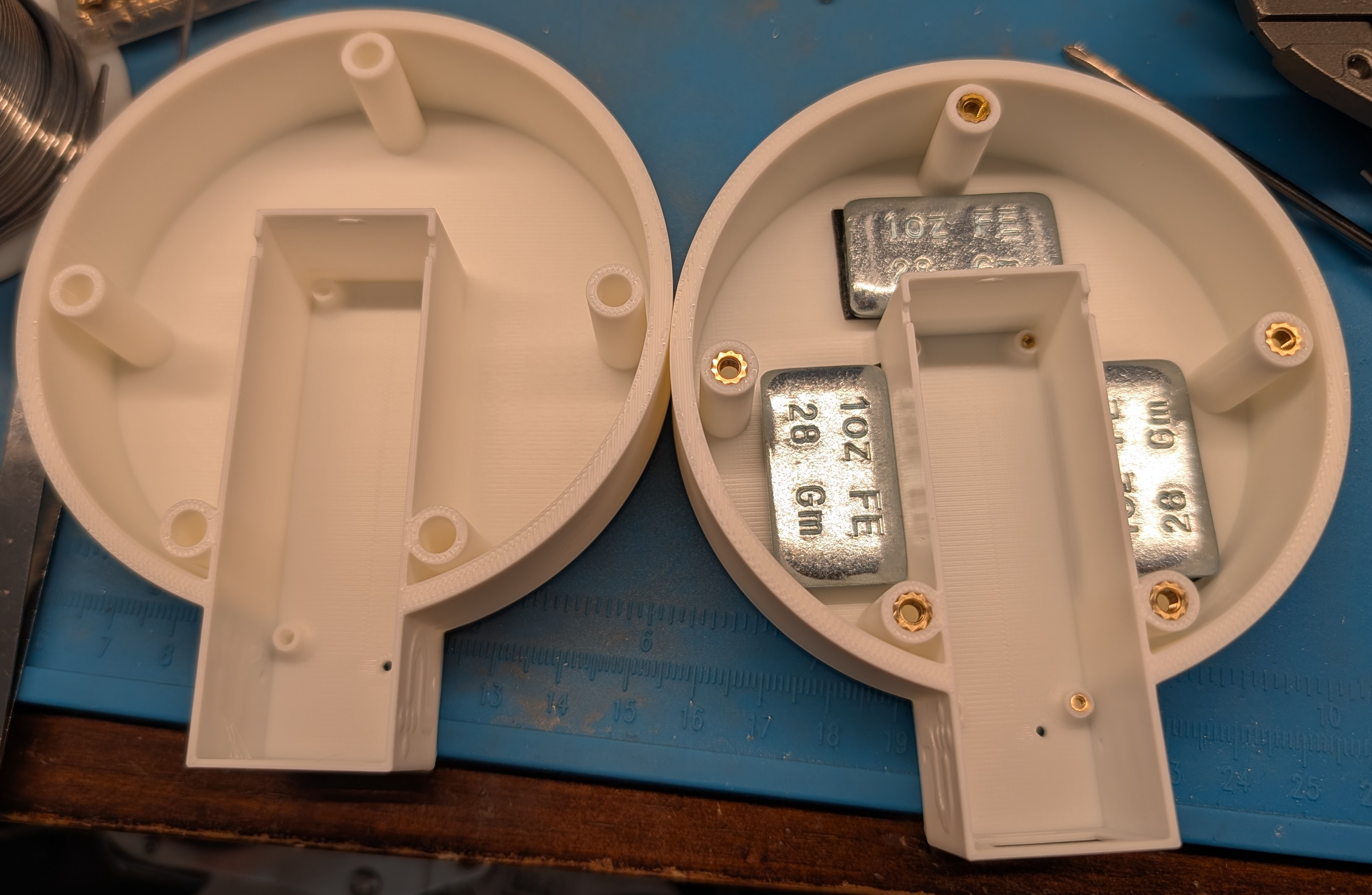
Press the brass heat-set inserts into the base with the soldering iron: M3 inserts into the lid-screw bosses, M1.6 inserts into the board anchor holes in the side pod. Optionally, stick the three 1 oz steel weights into the floor pockets; they are ballast so the unit stays put on a table instead of following the Ethernet cable around.
2. Mount the button and ring in the lid
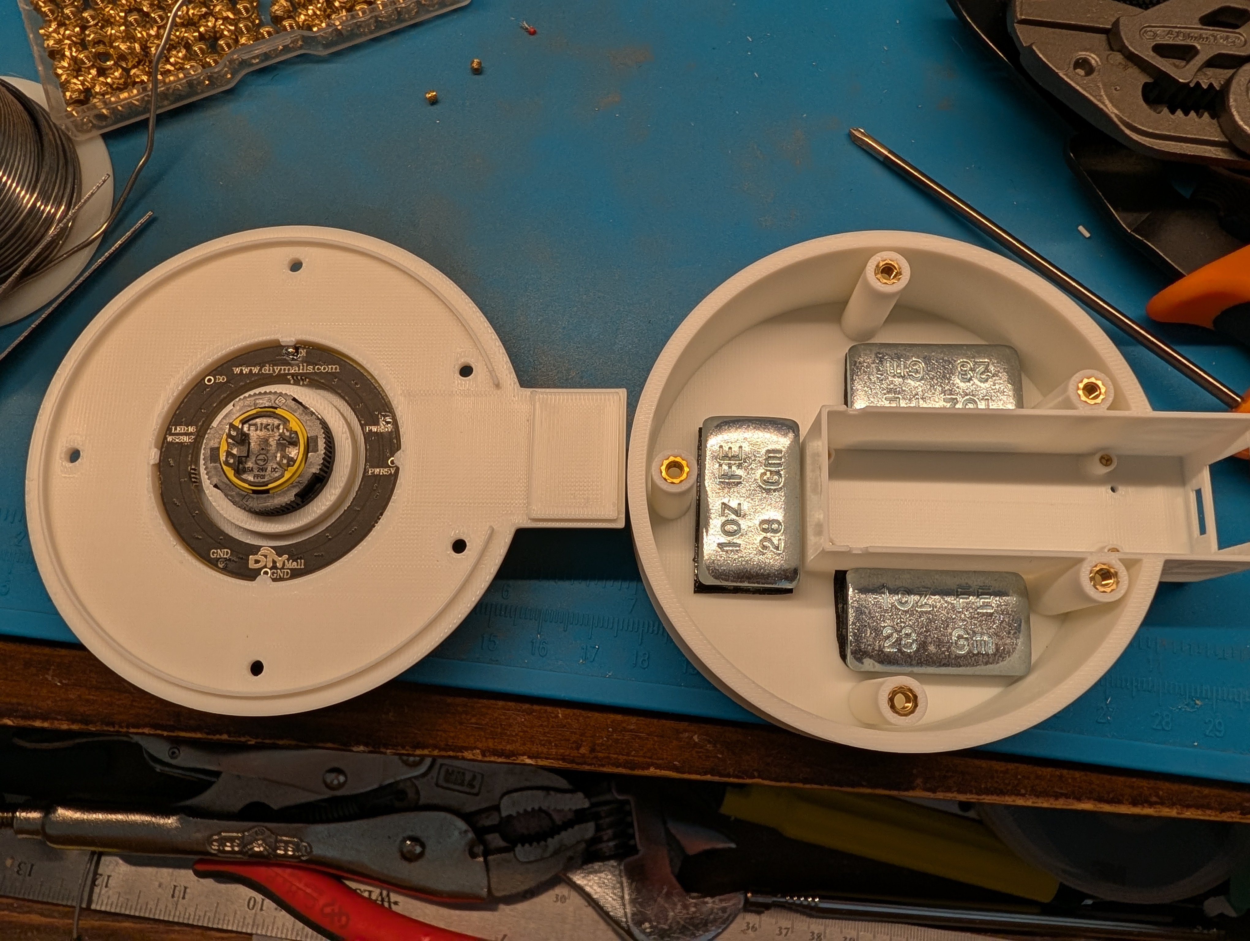
Push the E-stop button through the center hole from the top and lock it with its collar from below. Seat the LED ring around the button body, LEDs facing the diffuser. Rotation does not matter electrically, since which pixel counts as LED 1 is calibrated over the network after assembly; for consistency across units, match the orientation in the photo.
3. Solder the board wires and seat the board
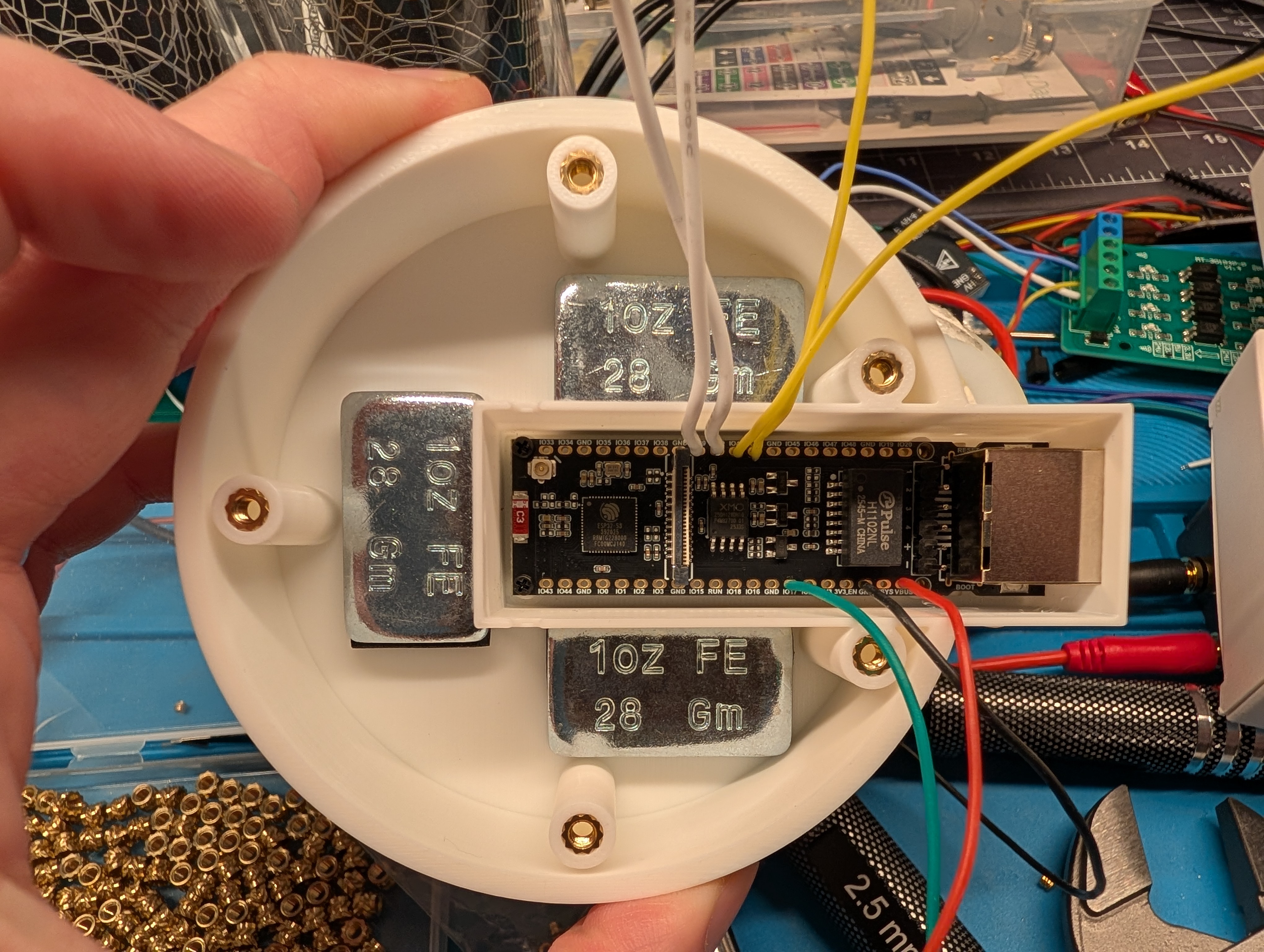
Solder the wires to the board pads first, leaving enough slack to open the lid comfortably:
| Wire | Board pad |
|---|---|
| red | VBUS |
| black | GND |
| green | IO17 |
| white x2 | IO39, IO40 |
| yellow x2 | IO41, IO42 |
Then drop the board into the pod channel, connectors facing out, and anchor it with the short M1.6 Phillips screws.
4. Install the PoE module and wire the lid
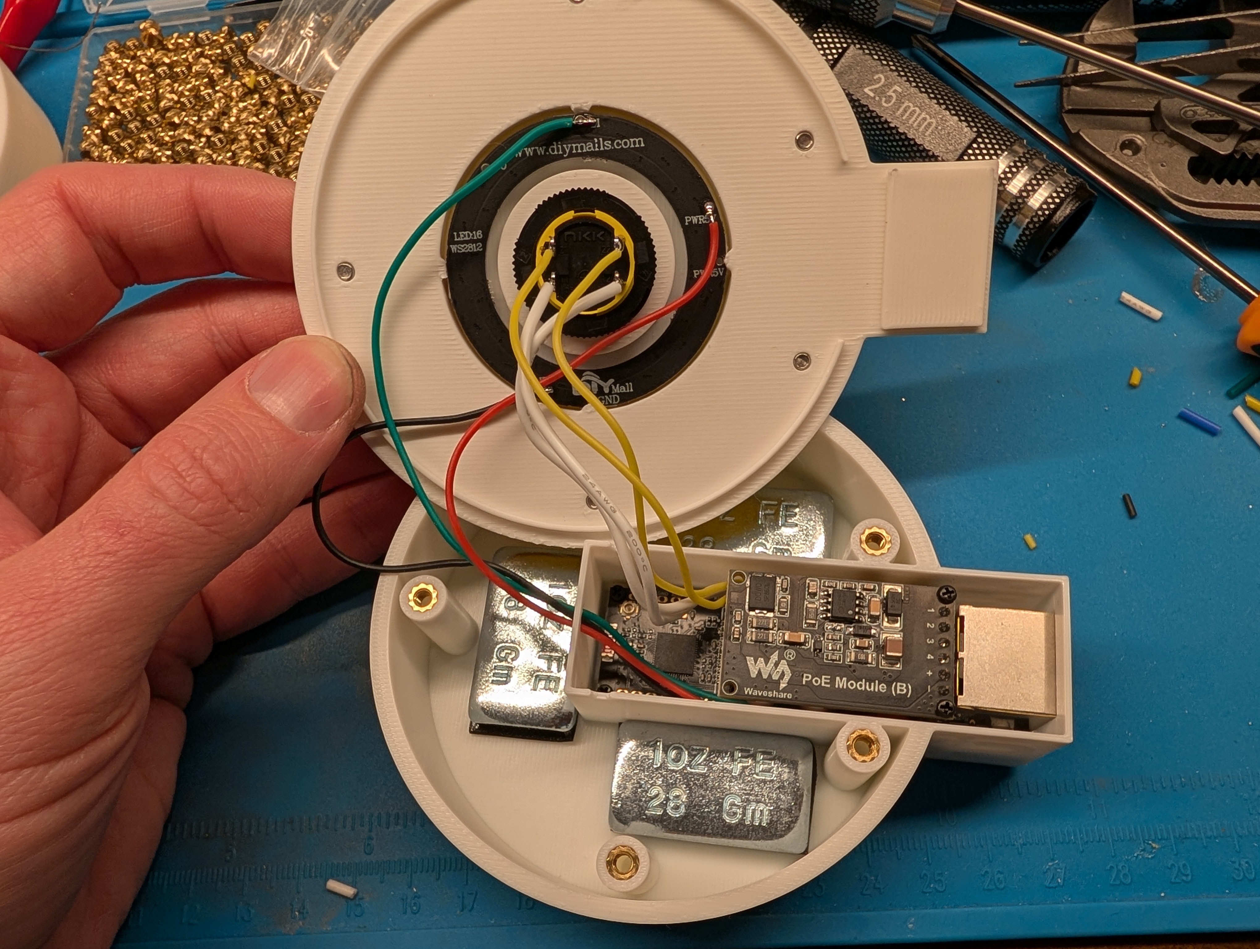
Set the PoE Module (B) onto the board and fasten it with the longer Phillips screws that come with the ESP32-S3-ETH; every unit gets the module. Thread the three ring wires (red, black, green) through the routing hole, then solder the connections: red to PWR5V, black to GND, green to DI (the ring has two PWR5V and two GND pads; either works, but mind the DI/DO marking, since data only enters at DI). The white pair goes to button terminals 11 and 12, the yellow pair to 21 and 22; within a pair, either wire on either terminal.
5. Close the lid
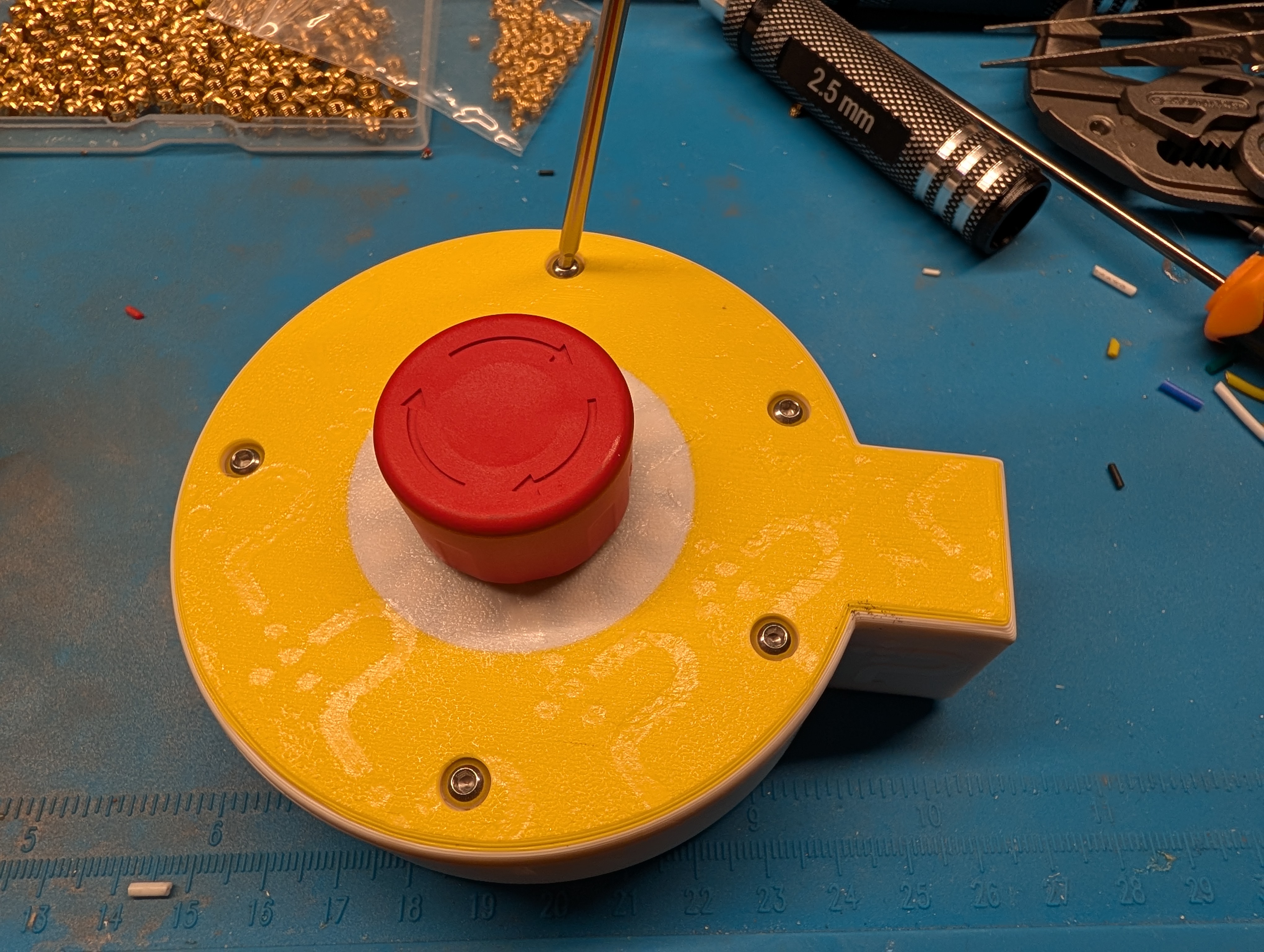
Fold the wires into the base so the lid does not pinch them, seat the lid, and drive the M3 screws into the inserts with the 2.5 mm hex driver. Snug is enough; the inserts strip before the screws do.
6. Commission
Connect USB and flash; a fresh board enters download mode on its own.
(If automatic flashing does not work, hold BOOT and tap RST to force
download mode.) Everything after the first flash goes over the network.
See the quickstart for the flash and
machine-pairing steps, then calibrate the ring rotation:
POST /api/ring_led1?on=1 lights the pixel the firmware currently calls
LED 1, and POST /api/ring_offset?n=0..15 moves it to where the bezel
says LED 1 should be (API reference).